This page created 28 Jul 2001; reformatted 20 Jan 2002
Applies to Versions 8 & 9
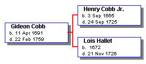
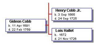
A standard box chart in Visual Chart Form (VCF) includes a number of boxes with text describing individuals, and lines connecting the boxes. Normally, all is well, but it is possible in editing a chart to get unexpected results. The most common issue I've found is that after I've moved a number of boxes around, what I expect to look like the chart on the left, instead has a connecting line that looks like the one on the right.
|
|
|
This example uses a chart with left-to-right orientation. But exactly the same issue, and solution, applies to charts with vertical orientation.
In order to understand what causes this problem, and how to avoid it, it helps to understand how connecting lines in VCF work. One might think that the lines connecting the three boxes above are made up of four straight-line segments - the three short horizontal lines and the longer vertical one. But actually, that is not the case. Rather, VCF constructs these connectors using three L-shaped line segments, as can be seen below:
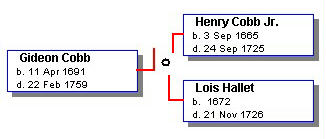 |
Usually the three segments meet at a node, which is normally not visible, but is represented above by the small circle. When you move the boxes, the length of the legs of the L-shaped segments adjust automatically so that they can stay connected to the node, and the connecting line appears to be a continuous forked line.
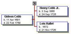
So how does one get the misshapen connector shown at the upper right? The answer is, by moving the boxes down, without moving the node. If the boxes are moved far enough, the node will be left above (or below) the place where the connector should turn into the box. As a result, all there L-shaped segments extend past where they should in order to stay connected to the node, and form the strange shape shown. The image below, with the node selected, may help in understanding what happens:
 |
Actually, there are two solutions – preventing the problem from occurring, and correcting it after it does.
To prevent it, simply make sure that all the nodes are selected along with the boxes they connect before moving anything. This happens automatically when you select a group of boxes by clicking and dragging the dotted line over the whole group, except sometimes for the nodes at the edges of the group. But if you select boxes individually by clicking on them, it is easy to miss selecting the node. If the node is not selected, and if you move the boxes far enough, you can generate this problem.
Once you find you have the problem, the solution is also simple. Just select the node (it should look like the example above). Then move it (down in the example above) so that it falls between the connectors to the boxes.
| ReigelRidge Home | Terry's Tips Home | Contact Terry |
Copyright 2000- by Terry Reigel